 21:29
21:29
 Unknown

Describing voltage and current relationships in electric circuits are often precisely analogous with the resultant equations when dealing with mathematical behavior of fluid-flow and heat-flow systems, the dynamic response of aircraft control surfaces and other non-electrical phenomena. Rather than building a prototype of the actual physical system, it is much easier and cheaper to construct the analogous electric circuit. As various elements are changed, the electric circuit may then be used to predict the performance of the other system.
One of the primary goals of this tutorial is to learn the methods of simplifying the analysis of more complicated circuits. Among these methods include nodal analysis, mesh, loop and superposition. In order to simplify the analysis, we investigate several different techniques for isolating specific parts of a circuit.
Nodal Analysis
Nodal Analysis is a systematic method for performing circuit analysis. It is also known as the node-voltage analysis or the branch current method which is used to determine the voltage between nodes in an electrical circuit. The basis of nodal analysis is the Kirchoff’s current law which helps determine all of the node voltages in a closed circuit.

The procedure for nodal analysis can be divided into three basic steps:
1. Label the node voltages with respect to a ground
2. Apply KCL to each of the nodes in terms of the node voltages
3. Determine the unknown node voltages by solving the simultaneous equations from step 2
Example 1:
Use nodal analysis to fond the voltage at each node of the circuit below.

Solution:
The bottom pair of nodes is actually 1 extended node making the number of nodes 3. The number of nodes is counted as shown below.

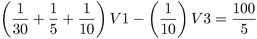
Node 2 will be assigned a voltage of zero and will be chosen as the reference node. For each node, Kirchoff’s Current Law is written down. The voltage at node 1 is V1 and the voltage at node 3 is V3 while V2 is zero. The following system of equations is the result:


The KCL applied at node 1 is the result of the first equation and the KCL applied at node 3 is the second equation result. By using the inspection method, this form for the system of equations could have been gotten immediately.

Example 2:

Solution:
As shown in the image below, the number of nodes is 4 and the node 4 is assigned a voltage of zero as the reference node.

For each node, the Kirchoff’s Current Law is written down, where V1 is the voltage at node 1, V2 at node 2 and so on. The resulting system of equations:


The nodal analysis does not accommodate a voltage source if you may have noticed. The voltage sources were defined with a small series resistor, representing internal resistance of the source in the early days. A clever method later hatched to include voltage-defined components call Modified Nodaly Analysis.
References
http://www.mathonweb.com/
http://upload.wikimedia.org/


2 comments:
dear friend, not what you are,
is what honors you.
How are you,
determines the value.
I wink, you sometimes just to,
and wish you a
magical Thursday, many greetings from Dieter
before doing nodal analysis everyone have must knowledge about what is node,branch and loop.
Post a Comment