Thursday 8 December 2011

How to Make a Simple Inverter

The inverter is an electronic circuit that converts DC voltage into AC voltage. The circuit is very useful when the power goes out or the time when we do not have an AC voltage source. Inverter only requires an accumulator to operate. So the advantages of this circuit (inverter) compared with an AC voltage generator that uses fuel to work is the inverter does not cause noise when being operated, does not cause air pollution and easier to carry anywhere.

So, how to make a simple inverter?

  1. We must learn the parts of an inverter. The parts of an inverter include: driver stage and power stage. You can see in the image below. 2.   Construct each of the parts of an inverter.
  •     Driver stage
Driver stage consists of pulse generator and pulse frequency regulator. We can construct a pulse generator with the IC 555 or other IC  that can generate pulses (one of the IC op-amp and IC TTL).

In the pulse generator, set the pulse frequency at 50 to 60 Hz by varying the component or add a potentiometer.

  •      Power stage
Power amplifier stage consists of current amplifier and step-up voltage. We can construct a current amplifier using a pair of transistors (Darlington transistor) with a reinforcement of the most good. In selecting transistors are used, we must choose a transistor that can work on the current that we use: for example we use a 10A current, we can use a 2N3055 transistor that can operate at currents up to 15A.

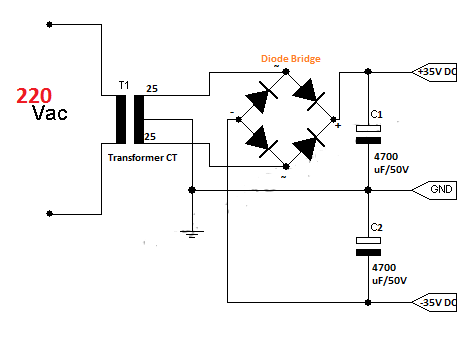
In the step up the voltage, if we want to construct a simple inverter, we can use the center-tap transformer with backwards mode to produce the 220 V output. If we want to construct a inverter with power 220 VA then we should know: Pinput = Poutput, where P = V x I, so the output voltage of the inverter circuit is 220 volts and have a current of 1 Ampere.

                                                        Pinput = Poutput

                                                    V in x I in = V out x I out

                                        12 V x   18,3 A  = 220V x 1 Amp

                                                     220 W   = 220 W

From the above calculation, we need the accumulator 12 V and have a current of about 18 A, we also need a transformer 20A to produce 220VA.

There are Inverter Selection :

Monday 5 December 2011

DC Motor Driver Using L298

This post has more to do about the microcontroller and its programs.

Here I will discuss how to drive the movement of a dc motor with the input of the microcontroller AT89S52 or ATMega? If we directly connect the microcontroller to the DC motor, the DC motor will not be able to move, it caused the output of the microcontroller has a low current rate of about mA. So, we need another component that can strengthen the output of the microcontroller. L298 is a simple DC motor driver is most appropriate to be used as a solution to this problem, because this IC can pass currents up to 4A and the voltage to 46 volts.

L298 is a dual full-bridge driver, said it's because it has two enable inputs, two pairs of input and two output pairs. We can see in the picture below:


Pins 5 and 7 is the first input pair, pins 2 and 3 are mining output pairs. To activate this section, enable at pin 6 must be logic hight (1), we can do this by programming the microcontroller and then connect it to a DC motor driver. For giving the source voltage to operate DC motors found on pin 4, this  pin can be bypassed with a voltage 46 volts and 4 amperes current. When we input logic 1 and 0 at each pins 5 and 7 then the output is also logic 1 and 0 in each of the pins 2 and 3. Well, by changing the logical substitute for diver then entered into a dc motor movement will also change.

see alse DC motor control, light detection with comparator circuit.

Thursday 1 December 2011

Adjusted The Servo with IC 555

Servo is a device that is widely used to create a project, which is associated with movement, such as tool motion on the robot, each using a servo joints. Servo motor movement is more subtle than the dc or stepper motor movements.
Most servo has a work rate of 50Hz (20ms) at the point where a pulse between 1 and 2ms is used for command output to drive the servo. We can build a simple circuit to adjust the servo movement can be built using IC 555.

We must be very familiar about this IC, because IC is widely used in applications as an oscillation, wave generator, timer, etc..
By adjusting the potentiometer on the circuit above, a 555 timer IC can generate pulses every 20ms with a duty cycle of between 5% and 10% (1-2ms). This circuit operates at 5-6 V as adjusted by a servo which operates between 5 and 6 V. if it exceeds the rate, this voltage will damage the servo.

This is its the PCB layout.


List of Components :

IC1 = IC 555; C1= 1 uF/16V ; C2 & C4 = 100 nF (ceramic); C3 = 390 nF; P1= 5K; R1= 2,7K; R2 = 68K; D1 = 1N4148.

Tuesday 15 November 2011

Generator Pulse with IC 555

Many devices or electronic components that can be operated with an electric pulse, even they can be adjusted by electric pulses. For example, a stepper motor, for controlling the stepper motor, required stepper motor controllers which produces periodic pulses.

Motor rotational speed is determined by the frequency applied to the stepper motor. Electric pulses can be generated by the oscillator circuit that uses a IC 555 with astable mode.
This circuit operates at voltage range 10-12 V. Frequency generated by this circuit can be calculated by the formula:
F= 1/1,44 {(P1+R4)+ (2(P2+R3)} C2
Duty cycle of this circuit can be adjusted by changing the value in P1 and P2, and the frequency also can also be changed by varying the value in C2.


D1,D2 = 1N4148; P1 = 50K; P2 = 50K; R1 = 220 ohm; R2 = 1K; R3,R4 = 100 ohm; C1 = 0.01 uF; C2 = 100 nF; C3 = 100 uF/16V ; IC = 555; J= jumper.

Monday 7 November 2011

MAKES A POWER SUPPLY 12V 5A

Today, when we want to make a device that uses a 12 volt voltage source, we can not possibly carry a large 12 volt PSA's everywhere. Now, to complement the tools that we make it, we must also make an appropriate voltage source with the tools we create.

Here, I will provide a circuit that can be used for devices that operate at a voltage 12 volts.
Many Power Supply circuits is also available on the Internet for free but may be making the circuit that requires a high cost, such as power supply circuit using the LM388, LM388 price per one unit rather expensive. I give this circuit requires only a low cost.

This is the its PCB layout.

Transistors can be replaced with another type with the desired current rating. For the type 2N3055 transistor is rated for currents up to 15A.

There are Power Supply 12V Selection :

Twitter Delicious Facebook Digg Stumbleupon Favorites More

 
Design by Free WordPress Themes | Bloggerized by Lasantha - Premium Blogger Themes | Bluehost Review