Showing posts with label Power Supply. Show all posts

Saturday, 7 July 2012

12V To 24V DC-DC Converter Circuit

This simple DC-DC converter can provide up to 24V from a 12V source. It can be used to run radios, small lights, relays, horns and other 24V accessories from a 12V vehicle with a maximum draw of about 800mA. It can be used to charge one 12V battery from another, or step up the voltage just enough to provide necessary overhead for a 12V linear regulator. Using one op-amp as a squarewave oscillator to ring an inductor and another op-amp in a feedback loop, it won't drift around under varying loads, providing a stable 24V source for many applications. With a wide adjustment in output this circuit has many uses.

Parts


Part


Total Qty.


Description


Substitutions
R1, R2, R3, R4, R8, R76100K 1/4W Resistor
R51470 Ohm 1/2W Resistor
R6110K Linear Pot
C110.01uF Mylar Capacitor
C210.1uF Ceramic Disc Capacitor
C31470uF 63V Electrolytic Capacitor
D111N4004 Rectifier Diode
D21BY229-400 Fast Recovery DiodeSee Notes
Q11BC337 NPN Power Transistor
U11LM358 Dual Op Amp IC
L11See Notes
MISC1Board, Wire, Socket For U1, Case, Knob For R6, Heatsink for Q1

Notes
  1. R6 sets the output voltage. This can be calculated by Vout = 12 x (R8/(R8+R7)) x (R6B/R6A).
  2. L1 is made by winding 60 turns of 0.63MM magnet wire on a toroidial core measuring 15MM (OD) by 8MM (ID) by 6MM (H).
  3. D2 can be any fast recovery diode rated at greater then 100V at 5A. It is very important that the diode be fast recovery and not a standard rectifier.
  4. Q1 will need a heatsink.
source :  www.aaroncake.net/circuits
Related Post :
1.2 - 36V / 5A Adjustable Power Supply
12V Portable and Mobile Power Supply Circuit Diagram
Charger Circuit Using LM 317 with Input 18V Battery

Power Supply Short Circuit Protection

Power Supply Short Circuit Protection


Description

This circuit designed to be used with:
0-30 Vdc Stabilized Power Supply With Current Control 0.002-3 A

Components values are shown in shematic.

Connect 741 +Vcc to D1 anode in main circuit
Connect 741 -Vcc to D3 catode in main circuit
U1 needs a 5v +Vcc connect pin 4 of U1 to 5v

Please note that +Vcc is above absolute maximum ratings of 741 which are +/- 22V, this may cause damage to OPAMP. You may need to add a LM7805 to power OPAMP. U1 needs at least 5v +Vcc.

Usage

- Power ON power supply then press START button to connect outputs to power supply.
- If output is shorted the relay disconnects output from power supply.
- Fix the short circuit and then press START again to connect output to power supply.

0-30 VDC STABILIZED POWER SUPPLY WITH CURRENT CONTROL 0.002-3 A

This is a high quality power supply with a continuously variable stabilized output adjustable at any value between 0 and 30VDC. The circuit also incorporates an electronic output current limiter that effectively controls the output current from a few milliamperes (2 mA) to the maximum output of three amperes that the circuit can deliver. This feature makes this power supply indispensable in the experimenters laboratory as it is possible to limit the current to the typical maximum that a circuit under test may require, and power it up then, without any fear that it may be damaged if something goes wrong. There is also a visual indication that the current limiter is in operation so that you can see at a glance that your circuit is exceeding or not its preset limits.

How it works

To start with, there is a step-down mains transformer with a secondary winding rated at 24 V/3 A, which is connected across the input points of the circuit at pins 1 & 2. (the quality of the supplies output will be directly proportional to the quality of the transformer). The AC voltage of the transformers secondary winding is rectified by the bridge formed by the four diodes D1-D4. The DC voltage taken across the output of the bridge is smoothed by the filter formed by the reservoir capacitor C1 and the resistor R1. The circuit incorporates some unique features which make it quite different from other power supplies of its class. Instead of using a variable feedback arrangement to control the output voltage, our circuit uses a constant gain amplifier to provide the reference voltage necessary for its stable operation. The reference voltage is generated at the output of U1.

The circuit operates as follows: The diode D8 is a 5.6 V zener, which here operates at its zero temperature coefficient current. The voltage in the output of U1 gradually increases till the diode D8 is turned on. When this happens the circuit stabilizes and the Zener reference voltage (5.6 V) appears across the resistor R5. The current which flows through the non inverting input of the op-amp is negligible, therefore the same current flows through R5 and R6, and as the two resistors have the same value the voltage across the two of them in series will be exactly twice the voltage across each one. Thus the voltage present at the output of the op-amp (pin 6 of U1) is 11.2 V, twice the zeners reference voltage. The integrated circuit U2 has a constant amplification factor of approximately 3 X, according to the formula A=(R11+R12)/R11, and raises the 11.2 V reference voltage to approximately 33 V. The trimmer RV1 and the resistor R10 are used for the adjustment of the output voltages limits so that it can be reduced to 0 V, despite any value tolerances of the other components in the circuit.
Schematic diagram
Another very important feature of the circuit, is the possibility to preset the maximum output current which can be drawn from the p.s.u., effectively converting it from a constant voltage source to a constant current one. To make this possible the circuit detects the voltage drop across a resistor (R7) which is connected in series with the load. The IC responsible for this function of the circuit is U3. The inverting input of U3 is biased at 0 V via R21. At the same time the non inverting input of the same IC can be adjusted to any voltage by means of P2.

Let us assume that for a given output of several volts, P2 is set so that the input of the IC is kept at 1 V. If the load is increased the output voltage will be kept constant by the voltage amplifier section of the circuit and the presence of R7 in series with the output will have a negligible effect because of its low value and because of its location outside the feedback loop of the voltage control circuit. While the load is kept constant and the output voltage is not changed the circuit is stable. If the load is increased so that the voltage drop across R7 is greater than 1 V, IC3 is forced into action and the circuit is shifted into the constant current mode. The output of U3 is coupled to the non inverting input of U2 by D9. U2 is responsible for the voltage control and as U3 is coupled to its input the latter can effectively override its function. What happens is that the voltage across R7 is monitored and is not allowed to increase above the preset value (1 V in our example) by reducing the output voltage of the circuit.

This is in effect a means of maintaining the output current constant and is so accurate that it is possible to preset the current limit to as low as 2 mA. The capacitor C8 is there to increase the stability of the circuit. Q3 is used to drive the LED whenever the current limiter is activated in order to provide a visual indication of the limiters operation. In order to make it possible for U2 to control the output voltage down to 0 V, it is necessary to provide a negative supply rail and this is done by means of the circuit around C2 & C3. The same negative supply is also used for U3. As U1 is working under fixed conditions it can be run from the unregulated positive supply rail and the earth.

The negative supply rail is produced by a simple voltage pump circuit which is stabilized by means of R3 and D7. In order to avoid uncontrolled situations at shut-down there is a protection circuit built around Q1. As soon as the negative supply rail collapses Q1 removes all drive to the output stage. This in effect brings the output voltage to zero as soon as the AC is removed protecting the circuit and the appliances connected to its output. During normal operation Q1 is kept off by means of R14 but when the negative supply rail collapses the transistor is turned on and brings the output of U2 low. The IC has internal protection and can not be damaged because of this effective short circuiting of its output. It is a great advantage in experimental work to be able to kill the output of a power supply without having to wait for the capacitors to discharge and there is also an added protection because the output of many stabilized power supplies tends to rise instantaneously at switch off with disastrous results.  

Parts List

R1 = 2,2 KOhm 1W
R2 = 82 Ohm 1/4W
R3 = 220 Ohm 1/4W
R4 = 4,7 KOhm 1/4W
R5, R6, R13, R20, R21 = 10 KOhm 1/4W
R7 = 0,47 Ohm 5W
R8, R11 = 27 KOhm 1/4W
R9, R19 = 2,2 KOhm 1/4W
R10 = 270 KOhm 1/4W
R12, R18 = 56KOhm 1/4W
R14 = 1,5 KOhm 1/4W
R15, R16 = 1 KOhm 1/4W
R17 = 33 Ohm 1/4W
R22 = 3,9 KOhm 1/4W
RV1 = 100K trimmer
P1, P2 = 10KOhm  linear potentiometer
C1 = 3300 uF/50V electrolytic
C2, C3 = 47uF/50V electrolytic
C4 = 100nF polyester
C5 = 200nF polyester
C6 = 100pF ceramic
C7 = 10uF/50V electrolytic
C8 = 330pF ceramic
C9 = 100pF ceramic
D1, D2, D3, D4 = 1N5402,3,4 diode 2A - RAX GI837U
D5, D6 = 1N4148
D7, D8 = 5,6V Zener
D9, D10 = 1N4148
D11 = 1N4001 diode 1A
Q1 = BC548, NPN transistor or BC547
Q2 = 2N2219 NPN transistor
Q3 = BC557, PNP transistor or BC327
Q4 = 2N3055 NPN power transistor
U1, U2, U3 = TL081, operational amplifier
D12 = LED diode
source : http://www.electronics-lab.com/projects/power/001/index.html
Related post:
1.2 - 36V / 5A Adjustable Power Supply
12V Portable and Mobile Power Supply Circuit Diagram
Charger Circuit Using LM 317 with Input 18V Battery

Friday, 6 July 2012

1.2 - 36V / 5A Adjustable Power Supply

Description

This is a very simple and adjustable voltage power supply. Max input voltage is 37V and output adjustable between 1.2 to (vcc - 3) volts.

Q1 is a power PNP Darlington transistor and is used to boost current of  LM317. It's the most useful adjustable regulator and for this circuit you can also use LM317L thats can give 100mA, thats enough for transistor bias.

D1 and D2 are protection diodes because when you turn the circuit off the output capacitors discharing and can damage the transistor or regulator.

R1 is 2W and other resistors are 0.25W

R1 is LM317 current limiting resistor and R2 is Q1 bias resistor all capacitors are 50V RV1 is 5k multi turn volume pot.

100nf capacitors are in parallel with electrolytic capacitors to remove high frequency noise because large value electrolytic have large ESR and ESL and cant remove high frequency noise.

I will design a pcb for this circuit and add to project .

Q1 need heatsink and small fan.
Circuit maximum output is 125W
source : http://www.electronics-lab.com/projects/power/021/index.html
Related Post:
12V Portable and Mobile Power Supply Circuit Diagram
Charger Circuit Using LM 317 with Input 18V Battery
Tuesday, 3 July 2012

12V Portable and Mobile Power Supply Circuit Diagram

A suitable 12V portable and mobile power supply circuit design is shown in the circuit diagram below. This type of power supply can be built quite inexpensively and needs only a minimum of circuitry. This circuit will give output current of 1 amp, well stabilized and smoothed.
The smoothing and regulation is provided by IC1 7812 which is a 12V monolithic voltage regulator. This portable power supply unit incorporates output current limiting and is therefore not damaged by accidental short term short circuits or other forms of output overloading.

12V Portable and Mobile Power Supply Circuit Diagram can be built using components as follow:
Resistor 1/3 watt 5%
R1 1.8k
Capacitors
Cl 2200uF 25V electrolytic
C2 100nF polyester (C280)
C3 100nF polyester (C280)
Semiconductors
ICI uA78I2 (12 volt 1 amp positive regulator)
D1 to D4 1N4002(4 off)
Switch
S1 DPST toggle type
Transformer
T1 Standard mains primary, 15 — 0 — 15 volt 2 amp secondary

Related post :
   
The Working Principle of Power Supply
Symmetric Power Supply +35V and -35V Project
Power Supply +12V. -12V and +5V
source : http://datasheetoo.com/power-supply/12v-portable-and-mobile-power-supply-circuit-diagram.html


Monday, 30 April 2012

Charger Circuit Using LM 317 with Input 18V Battery

Here is a simple but effective battery charger circuit using IC LM 317.The circuit can be used to charge 12Vlead acid batteries.The circuit is very simple and can be easily assembled on a general purpose PCB.

The heart of the circuit is IC LM 317 ,which is an adjustable voltage regulator IC.The pin 1 of the IC is the control pin which is used to control the charging voltage.The pin 2 is the output pin at which the charging voltage appears.The pin 3 is the input pin to which the regulated DC supply is given.

The charging voltage and current is controlled by the Transistor Q1,resistor R1 and POT R5.when the battery is first connected to the charging terminals ,the current through R1 increases.This in turn increases the current and voltage from LM 317.When the battery is fully charged the charger reduces the charging current and the battery will be charged in the trickle charging mode.

Notes:
    * The input voltage to the circuit must be atleast 3V higher than the expected output voltage.LM 317 dissipates around 3V during its operation.Here I used 18V DC as the input.
    * The charging voltage can be set by using the POT R5.
    * The LM 317 must be mounted on a heat sink.
    * All capacitors must be rated atleast 25V.
    * You can use crocodile clips for connecting the battery to the charger.

Source : http://www.circuitstoday.com


Saturday, 14 April 2012

The Working Principle of Power Supply

Perhaps many people or electronics hobbyist asked how the work of a power supply? Why wave generated can be straight vertical? voltage can be set and even can set the output current? Well, here I will discuss how it happened.
Components are very important in making a power supply are: transformer, rectifier, filter and regulator. Below is a general flow diagram of a power supply.

With the principle of magnetic induction, transformers reduce the voltage 220VAC to 30V, 18V, 12V and etc.. Based on the difference in the number of windings between the primary and secondary windings on the transformer, then the ratio of output voltage and input can be formulated as follows:

Vs/Vp = Ns/Np

After the voltage is reduced as expected, we have to convert the voltage into a DC voltage as the output voltage of transformer is an AC voltage. To change that, we need a rectifier component which is a diode. Diode will rectify AC voltage into DC, as shown below:
If using only a single diode is formed a half wave rectification. The output DC voltage can be formulated as follows:
Vrms = Vpeak / 2
Vdc = Vpeak / pi

If using a dioda bridge is formed a full wave rectification.

For the performance of the power supply is good, then the required voltage filter for filtering the voltage of the diode to be a straight vertical wave only. Component used is a capacitor.
How does a capacitor can be used as a filter? Based on the principle of charge and discharge. At the time of voltage entering the capacitor, at the time also the capacitor starts to charging the charge, and after that the capacitor will directly discharge  the charge. At the time of discharge, the capacitor will produce a voltage so the  rectification voltage is seen  decrease becoming increase, the event would occur continuously during the capacitor is given a voltage. The results of the working principle of  the capacitor produces the waves become more straight.
Related post :
Symmetric Power Supply +35V and -35V Project,
Power Supply +12V. -12V and +5V,
MAKES A POWER SUPPLY 12V 5A
12V Portable and Mobile Power Supply Circuit Diagram
Charger Circuit Using LM 317 with Input 18V Battery
There are Power Supply Selections:

Tuesday, 6 March 2012

Symmetric Power Supply +35V and -35V Project

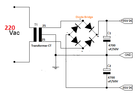
A symmetric power supply is needed when we make project about amplifier. Like an amplifier in sound system, it needs a symmetric power supply to operated. Here, we will construct a simple power supply circuit which result the output voltage is +35V and -35V.

This is the schematic and part of components


This project need a center-tap transformer, I recommend to use 3A transformer for good performances, 35 Amp of Diode Bridge for good rectifier, and 4700uF/50V Capacitor (If voltage of capacitor lower than output voltage, the capacitor will be explode, higher is better).
So this circuit is very simple, with 4 components you can construct a symmetric power supply.
NB:Be careful in the installation of components and wiring.

This is a proof of above project.


Related post :
12V Portable and Mobile Power Supply Circuit Diagram
Charger Circuit Using LM 317 with Input 18V Battery
The Working Principle of Power Supply
Power Supply +12V. -12V and +5V
MAKES A POWER SUPPLY 12V 5A

There are Power Supply Selections :


Sunday, 22 January 2012

Power Supply +12V. -12V and +5V

Schematic
The application of this circuit is in the use of operational amplifiers which require multiple power supply +12 V and -12V. It also still provides a +5 V power supply for other circuits such as digital circuits.
A symmetric power supply mostly used in amplifiers. If you want to create a symmetric power supply with a current of more than 1 amp, you would just remove IC79** and IC78** (output current of this IC is 1 amp), replace D1, D2, D3, D4 with a diode bridge with a range 35A, and replace the capacitor by increasing the charge and voltage.


PCB layout
List of Components
Names
Value
  Quantity

Transformer CT
15V, 9V
1
Voltage Source
Diode
1N4002
6
Rectifier
Elco
2200 uF/ 16V
3
Filter
IC1
LM7805
1
Positive Voltage Regulator (+5V)
IC2
LM7812
1
Positive Voltage Regulator (+12V)
IC3
LM7912
1
Negative Voltage Regulator (-12V)

Monday, 7 November 2011

MAKES A POWER SUPPLY 12V 5A

Today, when we want to make a device that uses a 12 volt voltage source, we can not possibly carry a large 12 volt PSA's everywhere. Now, to complement the tools that we make it, we must also make an appropriate voltage source with the tools we create.

Here, I will provide a circuit that can be used for devices that operate at a voltage 12 volts.
Many Power Supply circuits is also available on the Internet for free but may be making the circuit that requires a high cost, such as power supply circuit using the LM388, LM388 price per one unit rather expensive. I give this circuit requires only a low cost.

This is the its PCB layout.

Transistors can be replaced with another type with the desired current rating. For the type 2N3055 transistor is rated for currents up to 15A.

There are Power Supply 12V Selection :

Twitter Delicious Facebook Digg Stumbleupon Favorites More

 
Design by Free WordPress Themes | Bloggerized by Lasantha - Premium Blogger Themes | Bluehost Review