Monday, 27 February 2012

Minimum System of ATMEGA8

ATmega8 is a low power 8-bit microcontroller with RISC architecture. This microcontroller can execute a command dalah one period a clock for each instruction.
Some features of the ATmega8 are as follows:
1. 8 Kbyte Flash Program
2. 512 Kbyte EEPROM
3. 1 Kbyte SRAM
4. 2 8-bit timers and one 16 bit timer
5. Analog to digital converter
6. USART
7. analog comparator
8. Two wire interface (I2C)
Pin out of the ATmega8 can be seen in the following picture.

As we know, to make a usb downloader using ATMEGA8 we must have a minimum system of the uC. This circuit will help you to load the firmware to ATMEGA8.

This is the PCB layout of minimum system.
          Top view                                                                      Bottom view


NB : Value of the components are listed on the board and value of crystal is 8 - 12 Mhz

Sunday, 26 February 2012

Introduction Parallel and Serial (USB) Downloader

To flash the program into the AVR uC requires an equipment downloader. There are two types parallel downloader and serial downloader. Parallel downloader requires a computer that has a parallel port as DB25. Serial downloader can be used on any computer that has a serial port like a usb port.

Because now it no longer produced a computer that has a parallel port then we should make a serial downloader (usb downloader), advantages of the usb downloader is that it can be used on all computers because all computers have USB ports (portable), fast data delivery due to a computer now has a clock is high (> 1GHz). So do not worry about the delivery will be longer because the computer now has a high speed.

Example USB downloader for AVR

This downloader uses ATmega8, before ATmega8 programmed to change the serial to parallel resulting in MISO, MOSI, SCK, RESET to be connected to its target microcontroller. To program the ATmega8 also requires a minimum system, after a series of programmed and then transferred to the usb downloader circuit.

But before it has a serial downloader, you can also program ATmega8 using parallel downloader, downloader parallel circuit is found the internet for free and does not require a programmable IC.

Wednesday, 22 February 2012

AVR Minimum Kit Ready to Used

If you want to learn about the AVR but does not have its minimum system kit or you do not have much time to make it. Here I offer minimum AVR system kit at a price of $16. If you are interested, you can email me or leave a comment.

This is a picture of the product


If want to create your system with yourself, here are pictures of the PCB layout
The kit can be used for ATmega8535 or ATmega32 microcontroller.

Thursday, 16 February 2012

Example Project with Eagle 3D

USBasp


 Minimum System of ATMEGA8


 50W Amplifier


AVR and The Minimum System


The above picture just pictures, not to go to the trade.


You can get a tutorial from this link http://www.societyofrobots.com/electronics_Eagle3D_tutorial.shtml, I learn the article in there and now I can construct my project to 3D view.

Wednesday, 15 February 2012

A Simple 50W Amplifier Circuit

Amplifier is a device to increase the power of signal by using external energy sources. It can be used to strengthen the voice of a musical instrument or other sound source to connect the speaker on its output.
This is a simple Amplifier which is built with LM741, transistors are connected in such a way that produces 50W of power.


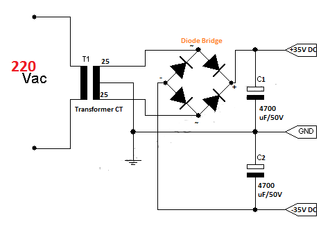
For good operation, the circuit requires a symmetrical power supply (+30 V and-30V) with a range of 3A of current( for mono, if you want stereo use power supply with 5A of current).
The circuit above are C1 = 4.7 uF at the input, if you want to lower frequency signals that increase the value of C1, or if you want to strengthen the higher frequency signals then decrease the value of C1. Potentiometer (R9) to adjust output signal of amplifier ( frequency and amplitude). Input (IN) of the circuit can also be a signal from signal generator.


List of Components :
R1,R4 =1K ; R2, R8 = 50K ; R10, R12, R13, R15 = 50 ohm ; R3, R6 = 2K ; R5,R7 = 15K ;  R11, R14 = 500 ohm ; R9(Potentiometer) = 1K ; C1 = 4.7uF/25V ; C2 = 100uF/25V ; C3,C5 = 47uF/25V ; C4 = 10 pF (ceramics) ; D2,D3 (Zener) = 15V ; D1,D4 = 1N4148 ; T1 = 2N3055 ; T2 = 2N2955 ; T3 = 2N4037 ; T4 = 2N3053; IC= LM741

Note: We can substitute components with other components that have the same specs.


Monday, 6 February 2012

Inverter 100W with IC 4047

This is a schematic inverter 100W, to produce 100W of power we use 12V10A car battery. R1 is a potentiometer that is used to set the output frequency to be at 50-60 Hz, which the inverter will be used for our home electronics. If only to try, you can use the step-down transformer CT in reverse, the input at 9V-0-9V and the output at 220V. Transformer 10A that we must use in order to produce 100W of power. This Circuit is built with a 4047 to generate pulse, two of 2N3055 and a transformer  to increase power. You can replace the transistor with other transistor if have a same spec.

list of components:
IC 1        4047
R1          250K Potensiometer
C1          0.022uF/25V
R2,R3    10 ohm, 5 watt resistor
C2,C3    68 uF/25V Tantalum Capacitor
Q1,Q2    2N3055 NPN Transistor
TR1        see text

This inverter can be designed to produce greater power in a way by substituting transistors and transformers (power stage) are more powerful components.
Note: use a heat sink to each transistor for a good performance 

There are Inverter 100W Selections : 

Twitter Delicious Facebook Digg Stumbleupon Favorites More

 
Design by Free WordPress Themes | Bloggerized by Lasantha - Premium Blogger Themes | Bluehost Review