Thursday, 26 January 2012

AVR and The Minimum System

AVR is a microcontroller family which is now the most widely used. The concept of the AVR architecture was originally created by two students at Nerwegia Institute of Technology (NTH) that is Alf-Egil Bogen and Vegard Wallen which later developed by Atmel. Until now Atmel AVR family has issued few, the latter is a family of 32-bit RISC AVR. One family of AVR 8-bit microcontroller that is often used is ATMEGA8535/32.

That makes this microcontroller family of widely used people are :
  1. Have a Flash, a EEPROM, and a SRAM are all in one IC, so that in certain applications do not require external memory. 
  2. Program execution faster because nearly all instruction is conducted in only one or two clock cycles different with MCS-51, which performs instruction in 12 clock cycles. 
  3. Has many useful features, for example on ATMEGA8535, look at features
Click on the pictures to zoom in

The Minimum System of AVR


The minimum system circuit is a minimal circuit  where a microcontroller chip can work (running). Circuit is called minimal because of the use of hardware components that are used are the most minimal requirements for a processor to work. Actually AVR ATmega chip is equipped with an internal oscillator, so, to save costs (cost), no need to use a crystal / resonator external to source clock the CPU. But for good performance or we apply to projects that require a different oscillator with internal oscillator chip so we must use an external oscillator.
List of Components:


Name
Value
Quantity
uC (AVR)
ATMega8535/32
1
crystal
12Mhz
1
capacitors
30pF
2
elco
10uF
1
resistors
470
2
led

1
voltage regulator
LM7805
1
pin header
see pictures

If you have a downloader (serial or parallel), connect to the MISO. MOSI, SCK, RESET on the microcontroller (J1 in minimum system). Then to flash the program into the AVR  can use the software ISP flash-programmer v.30a. (free download)

Sunday, 22 January 2012

Power Supply +12V. -12V and +5V

Schematic
The application of this circuit is in the use of operational amplifiers which require multiple power supply +12 V and -12V. It also still provides a +5 V power supply for other circuits such as digital circuits.
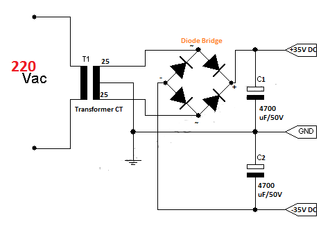
A symmetric power supply mostly used in amplifiers. If you want to create a symmetric power supply with a current of more than 1 amp, you would just remove IC79** and IC78** (output current of this IC is 1 amp), replace D1, D2, D3, D4 with a diode bridge with a range 35A, and replace the capacitor by increasing the charge and voltage.


PCB layout
List of Components
Names
Value
  Quantity

Transformer CT
15V, 9V
1
Voltage Source
Diode
1N4002
6
Rectifier
Elco
2200 uF/ 16V
3
Filter
IC1
LM7805
1
Positive Voltage Regulator (+5V)
IC2
LM7812
1
Positive Voltage Regulator (+12V)
IC3
LM7912
1
Negative Voltage Regulator (-12V)

Thursday, 19 January 2012

Stepper Controller

Stepper is an electromechanical device that works on electrical pulses that periodically flows into the motor, then each pulse is converted into motion, that's why it is called a stepper. Stepper motors are discussed is a unipolar stepper motor which has 4 phases and the length step of 1.8 ° per step (phase). The smaller the step length per step of a stepper motor, it is the better.

Stepper motors have many advantages than DC motors. Some of these are: easier to manage and can result in a slow rotation. Therefore, in certain applications more and more people choose to use stepper motors than DC motors.

In order to move the stepper motor can rotate then the pulse is given as shown below

look a video demonstration

To generate a periodic pulse above, there are several ways:
  1. Using IC 555 as a pulse generator, and amplifier circuits (solid state switches) because the stepper motor requires a sufficiently large electric currents between 1 to 2 Amp.
  2. Using a IC microcontroller that has been programmed to generate pulses at its ports.
Here will be discussed using IC microcontroller AT89S51.

Port 0 uC is connected to the data of stepper motor as shown in the figure below. Between uC and stepper motors are IC ULN2803, this IC will provide the voltage supply data from the uC to a stepper motor because without this IC, output voltage of the uC will not be able to drive a stepper motor stepper motor, although it has given voltage 12V.

Programs generate pulses to drive a stepper motor:

start:
mov a, #1                            ; fill the accumulator with the value 00000001
mov r1,#4

main:
mov P0,a                             ; fill P0 with values ​​in the accumulator
rl a                                       ; rotate left  the accumulator value by one bit.
Call delay                             ; call delay, because rotate process need times
djnz r1,main                          ; decrease the value in register 1, if not zero then jump to the main
sjmp start                              ; if the register 1 is zero then a jump to start, re-fill the values of the accumulator and register 1

delay:
mov r2,#255
dly :
mov r3,#20h
djnz r3,$
djnz r2,dly
ret
end

Code rl  a on the above program is a primary function to generate a periodic pulse that will make the stepper motor rotates.

Port 0     P0.0     P0.1    P0.2       P0.3
Rl a          1           0         0           0
Rl a          0           1         0           0
Rl a          0           0         1           0
Rl a          0           0         0           1

look a video demonstration

Thursday, 12 January 2012

Design Electronic Circuit Software

If we want to create an electronic circuit, the first thing done is to construct a circuit board on the project in order to alter the value and its components. Then after it obtained the proper circuit so that the circuit is not disturbed, we designed it on the PCB board.

There are many of software used to design electronic circuits. Here we will discuss two software are often used to design electronic circuits, both in making the circuit schematic and PCB layout.

1. Eagle

Eagle is a popular software in designing electronic circuits. In the eagle there are schematic and PCB layout design. In the latest version of the eagle, Eagle V6 has been there Autorouter feature to run the simulation.

Schematic design examples using the eagle

Example of PCB layout design using the eagle
2. Proteus
In addition to designing electronic circuits, Proteus can also run a simulation on a design that was built, by pressing the play button on the design that has been created then the simulation runs.

Schematic design examples using the Proteus

Example of PCB layout design using Proteus
The difference between these two software are:
  1. In designing the circuit schematic, easier to use Proteus. Necessary components are easy to find in Proteus, so the job drawing schematic more quickly resolved.
  2. In designing the PCB layout easier to use the eagle as it's easier to set the components used. In the eagle there also present conversion schematic to the PCB board or board to the schematic if we begin by drawing a schematic or board.
  3. If our purpose in running simulation circuits, easier to use Proteus.
  4. Eagle has a 3D-visualization features, these features can make real form (3D) of the components that are designed on the PCB, so using Eagle for the purpose of making a PCB layout more attractive.

Friday, 6 January 2012

DC Motor Controller

In the previous discussion about dc motor driver with L298 explained that, dc motor can be set by the L298 motor driver. To adjust the movement of the motor automatically needed circuit that combines the IC Microcontroller and L298.

Many types of IC microcontrollers that can be used to perform this work. Here are discussed using AT89S51 as the  IC control. This IC can store data for 4Kbyte. Data entered into the microcontroller is made ​​with a program which is then converted to a file. Hex, this file will be flashed into the  IC control.

The following is a simple motor control circuit.


To flash the program from the PC (Personal Computer) to the IC control needed downloader that is connected to the MISO, MOSI, SCK, RESET, VCC and GND of the IC control.

This is a list of programs to control the dc motor automatically using assembly programming :

Start:

motor_right:                      ; dc motor rotates to the right
mov p1,#00000001b          ; p1.0 = 1  and p1.1 = 0
call delay                          ; call times
mov p1,#0ffh                    ; stop
call delay                          ; call times
motor_left:                        ; dc motor rotates to the left                                                 
mov p1,#00000010b          ; p1.0 = 0 and p1.1 = 1
call delay
mov p1,#0ffh                     ; stop
call delay
sjmp start                           ; jump to start

delay :                                ;times
mov r1, #255

dly:
mov r2,#100
djnz r2, $
djnz r1,dly
ret
end

Tuesday, 3 January 2012

Designing a light-detection circuit

In designing a circuit that can detect light, the most important component is the light sensor. One of the light sensor that we often encounter is LDR (Light Dependent Resistor).

Introducing the Light Sensor

LDR resistance changes with changes in light intensity hit it. In the dark, the LDR resistant is about 10 Mohm and the sunniness of 1 kohm or less. LDR is made from semiconductor materials such as cadmium sulfide. With this material, the light energy that falls cause more load is released or the electric current increased payload. That is, the resistance of the material decreases.
LDR is used to convert light energy into electrical energy. Automatic switches and burglar alarms are a few examples of tools that use the LDR. Because the response to light enough slow, LDR is not used in situations where the light intensity changed drastically.

Characteristics of LDR:

1.   At the time not given light, LDR has a very high resistance could reach 10 Mohms
2.   But when given a light, the barriers will come down drastically so that the voltage and current can pass through the LDR.

So how do we use the characteristics of the LDR to construct a light detector circuit?
Surely this LDR will be combined with other components. Here is an example circuit with LDR and other components.

 From the picture above, we can set (varying) the value of R1, R2 and potentiometer P1.

V+ = (RLDR / R1 + RLDR ) 5V

V- = (P1 / R2 + P1) 5V

For example we want to turn on lights automatically when dusk and the lights off automatically when the early morning. Here we can set the reference voltage to be compared with the input voltage of the LDR, we can set these voltages to match the surrounding light intensity.

Twitter Delicious Facebook Digg Stumbleupon Favorites More

 
Design by Free WordPress Themes | Bloggerized by Lasantha - Premium Blogger Themes | Bluehost Review